The following is a combination of images and transcribed text from a set
of treadle plans and instructions that were originally downloaded from Randy
Smith's website. On it he has some interesting insights into how he eventually
made his kick-wheel (not a treadle wheel as pictured below). One point of interest
and may be useful to modify the treadle wheel design is his description of using
a pillow-block
bearing. I hope these plans prove useful.


KICK WHEEL
The delight of the kick bar on this wheel is adjustable, which makes it suitable for most people. If the thrower is very small or extremely tall the overall dimensions can be adjusted without detriment to the wheel.
You may save a lot of money if you are able to find good quality materials and lumber, but no compromise should be made when making the shaft, which should be made to the highest standards. If the shaft is badly aligned the wheel head will oscillate.
Flywheel
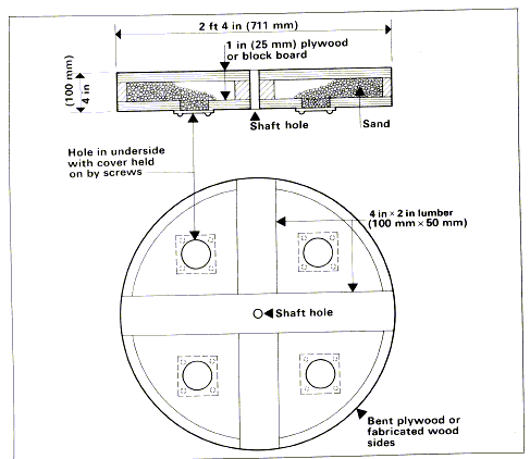
The standard flywheel is 2ft 4 inches wide and 4 inches

deep. It should be made of planks glued and screwed at eight angles to each other. Use the cheapest lumber available. If a heavy flywheel is require make it deeper and/or ad lead weights to the outer rim.
This makes an average weight flywheel. The dimensions can be altered depending on your requirements. If you normally make large quantities of small pots I would recommend the righter flywheel. A heavier flywheel is more suitable for making larger pots.
A hollow flywheel that can be filled with varying amounts of ballast can easily be constructed. (See Fig. 14) This has the advantage of enabling you to
Figure14. A flywheel with adjustable weight, for the kickwheel.

Experiment and choose and ideal weight of flywheel which suits you and the type of ware that you are making. For making quantities of small pots a light flywheel is an advantage as a heavy one has too much momentum and continually stopping and starting it can be tiring. When making large pots a heavy flywheel is an advantage as its greater momentum gives smooth slow running with less kicking, which is ideal for the more lengthy process of making large ware.
This flywheel should be made as shown in Fig.14. The side can be made from a strip of thin plywood. This is soaked in water so it can easily be bent to shape. If a bandsaw is available the side can de laminated from short pieces of wood glued together. When the clue is dry the whole flywheel is cut to shape including the top and bottom panels.
Shaft
The shaft is made of 1 inch round steel as shown in fig15. A local small engineering works, blacksmith or agricultural engineer are the ideal people to make the metal work for this wheel.
The shaft joints should be welded whilst the shaft is turning slowly, so the weld is even and no stresses are set up in the metal. The shaft is made with section R in place which is only removed adapter all the welding has been compelled. The shaft's crank is offset by 3 inches, which gives a smooth fairly fast running wheel head. If this is decreased by up to 3/4 inch it will run faster; if it is increased by up to 1 inch the wheel will run slower. However, the 3 inch offset suits most people. The plates(see S on Fig. 15) are 2 inches wide.
The wheel head fitting, M in Fig. 15 is a no.3 Morse taper. the other standard fittings are a 3/4 inch Whitworth screw and 20mm continental screw. (In the U.S. there is no such stardardized taper and the cost for milling one would be exorbitant. It is possible to use standard set screws alone as wheel head fittings.)
Kick bar bracket C
this is made of 2 x 1/4 inch angle iron. It has three screw holes in it by which it is attached to the leg of the wheel. It has a split pin 1/2 inch from the top of the peg. This is to retain the kick bar.
 |
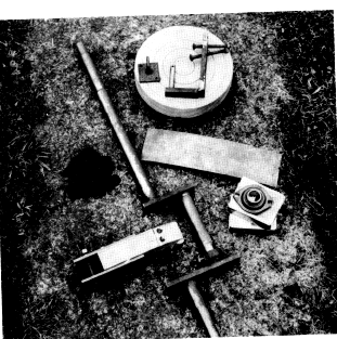
Shaft, crank connector and leather strip, kick bar bracket, hook and chain, bearings and hardwood wheel head. Note that on the crank of the shaft there is an adjustable sleeve. This is not essential but it helps keep the crank connector in place. |
Crank connector D plus A, B and L
The crank connector is made of a 2 x 3 inch piece of wood and is held onto the kick bar by metal plates A and B. A 1/2 x 3 1/2 inch long carriage bolt passes through the large holes on plates A and B, and through the kick bar the attachment to the kick bar can be made adjustable by drilling several holes in the kick bar. Eight holes at 2 inch intervals, the firs one being 4 inches from the kick bar pivot peg will give the wheel a range of kicking actions. Depending on the height and built of the throw, one of these holes well prove to be suitable. The connector is held onto the shaft's crank by a strip of leather, Part L , by two screws or bolts (see Fig. 15).

Assembly Notes
| A | Cut all wood for frame (except cross-ral) and cut tenon joints where applicable. |
|
||||||||||
| B | Cut Mortice Joints | |||||||||||
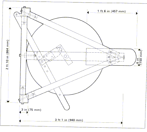
| C | Assemble frame. For a very rigid and permanent fixture the joints can be glued and doweled. If you wish the wheel to be taken apart at a future date the joints should be left dry and carriage bolts used to secure them. For some parts it may be more convenient to use lag bolts. When finished the wheel is 2ft. 10 inches wide. If it will not pass through your door frame the joints are best left dry and carriage-bolted. | |||||||||||
| D | Cut 1 1/2 inch holes for the shaft in the top and bottom rails, fit bottom bearing and put shaft in position. | |||||||||||
| E | Make and put put flywheel in position. | |||||||||||
| F | Lag bolt flywheel to shaft and tighten bottom bearing onto shaft. | |||||||||||
| G | Fit top bearing and tighten onto shaft. |
Materials
Wood -- either a good softwood or hardwood
124
|
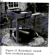
The sequence of photographs shows Medway College of Design ceramic students constructing a kickwheel. 1-4 Assembling the frame. The mortise and tonon joints should fit tightly. The joints are carriage bolted, which means the wheel can be taken apart. 5 Filling the adjustable weight flywheel with balast. Most potters like a heavy flywheel. 6 Compelling the wheel by fixing the seat, bearings, shaft and flywheel. 7 The completed wheel with its kickboard and crank connector. For this wheel we made a metal and hardwood connector; the leather and wood connector is easier to make and works as well. The wheel was completed with a turned hardwood wheel head. A local engineer turned a small metal shank to fit the head on the shaft. The tray was panted with several coats of polyurethane varnish.
|
